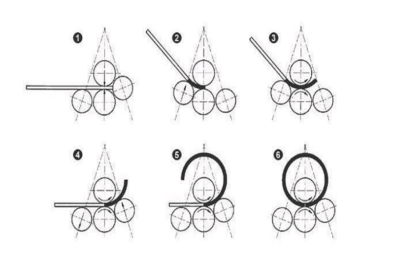
The steel plate rolling machine is specialised equipment for shaping sheet metal. The upper working roll is the core component for completing the rolling process. When subjected to significant forces during rolling, it may experience deflection, resulting in uneven pressure distribution on the steel plate and leading to the production of substandard items. Current methods for reducing deflection primarily include.
1. Designing the Upper Working Roll With A Barrel Shape
During design, the working section diameter of the roll tapers gradually from the centre towards both ends. When rolling, the upward bending force applied to the upper roll causes upward deflection, which is precisely counteracted by the barrel-shaped central section. This maintains the upper roll in a substantially straight state.
This approach is widely adopted in plate rolling machines and favoured by most designers. While it provides effective compensation, its implementation involves complex calculations and manufacturing challenges.
2. Adding Supports to the Upper Working Roll
This method involves installing support beams and support rolls beneath the upper working roll. By adjusting the height of the support rolls, a predetermined downward pre-deformation is induced in the upper working roll. This deformation precisely counteracts the upward deformation occurring during plate rolling, thereby achieving deflection compensation.
This approach is predominantly employed in specialised plate rolling machines handling larger width dimensions, such as those used in shipbuilding or for forming petroleum storage and transport tanks. It is only suitable for rolling curved plate sections or workpieces with large cylinder diameters.
3. Installation of Elevating Supports
This method involves fitting elevating support beams and support rolls to both the upper and lower working rolls. During edge pre-bending operations, where significant forces are applied, causing deflection in the working rollers. Lowering the support beams then provides support to the upper working rollers, reducing their deformation. After pre-bending, when rolling the cylinder, the support beams are raised, allowing the cylinder body to pass between the upper working rollers and the support rollers.
This method is suitable for workpieces requiring pre-bending of plate ends with smaller cylinder diameters.
4. Utilising Counterpressure
This method employs counterpressure to reduce deflection of the upper work roll. Two hydraulic cylinders mounted externally on the frame apply vertical counterpressure to both ends of the upper roll, inducing downward bending deformation in its central section. This compensates for deformation caused by insufficient upper roll deflection.
The advantage of this approach lies in its ability to dynamically adjust compensation according to load variations. However, it presents drawbacks including complex mechanical design, significant engineering challenges, and higher manufacturing costs. While foreign companies have produced such models, only a limited number of domestic manufacturers currently offer them.
Each of the aforementioned methods possesses distinct advantages and disadvantages. In practical design applications, the selection of an appropriate solution should be based on the specific operating conditions of the plate rolling machine and the associated manufacturing costs.